Modern Load-bearing Walls and Pillars
Section outline
-
-
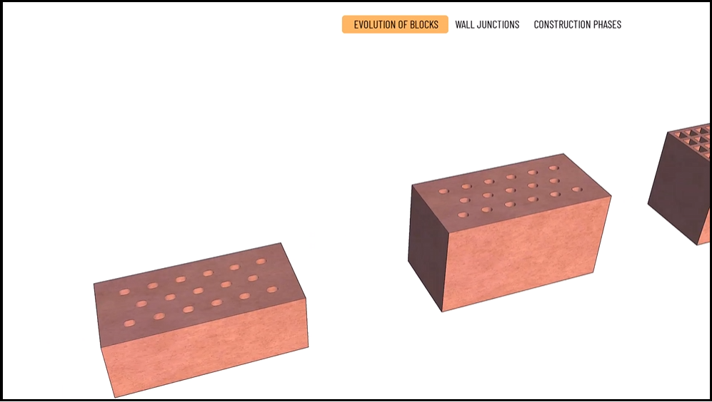
1. The evolution of blocks
Fired clay bricks underwent a spectacular evolution over the 20th century until they became the masonry blocks of today. Taking advantage of the technological advances in mass production, the main directions of innovation have been towards better thermal insulation and faster and more efficient construction. First, the holes appeared in the bricks, as the air cells provide the bricks with excellent thermal insulation properties. One of the following steps was to increase the height of the bricks, resulting in fewer courses to build, speeding up the construction process. The increase in the number of cells, and thus the cell ratio, further increased the insulating properties.
At the same time, sizes continued to increase as the large number of cells significantly reduced the specific mass. For most manufacturers, the height has remained constant at around 23.8 centimetres, assuming a mortar thickness of 1.2 centimetres and, thus, a vertical grid size of 25 centimetres. The blocks have also been widened in both directions, further facilitating construction: the 30 or 38 centimetres thick walls should be placed in a header course instead of a varied brick bond.
The mortar pocket appeared in many blocks, making vertical joints unnecessary. The same result is achieved with the tongue-and-groove joints. Eliminating vertical joints improves thermal properties and speeds up construction on site.
The developments’ next focus was to reduce bed joints to a minimum. The latest blocks are precision-planed, keeping the height grid at 25 centimetres, thus reducing the height of the joint to 1 millimetre instead of 1.2 centimetres. The mortar is now applied with a roller, or adhesive foam strips are sprayed between the courses. The lower material and water requirements also mean a more economical and environmentally conscious approach.
In line with the insulation requirements, the wall thickness has also been steadily increased to meet these needs without needing separate insulation. 44-centimetre wide blocks soon joined the 30 and 38-centimetre walls. The EU's current requirement for the U-value can be met by a wall built of two types of blocks without thermal insulation:
-
A tongue-and-groove, 44-centimetre-wide, precision block with an innovative cavity system.
-
A tongue-and-groove, 44-centimetre-wide, precision block with a core that has internal rock wool cells instead of air cells. Thus, the thermal insulation is integrated inside the block.
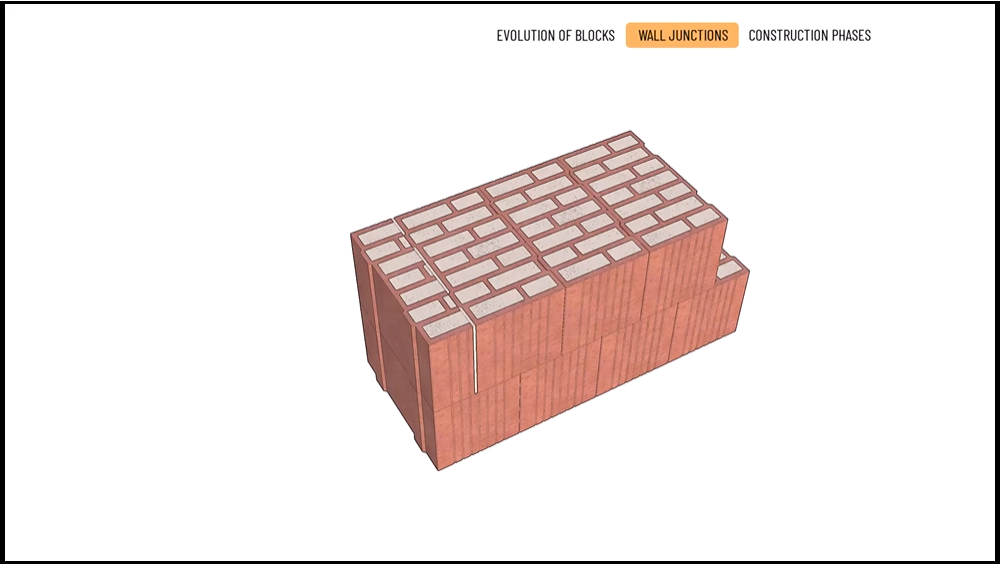
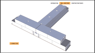
2. Wall Junctions
The following example shows a 44-centimetre-wide clay block wall end, a wall corner and a Tee-connection with another 38-centimetre-thick wall. We have chosen precision-planed blocks with internal rock wool insulation. For the masonry, we follow the general rules of good wall bonding. First, we figure out how we will solve the critical wall junctions.
a) Wall ends
You don't need to think much about the wall end for either wall 38 or 44. In the courses of the wall, we want to keep a half offset between the headers, so we place whole blocks in the starting course and start the next course with a half closer.
b) Wall corner
One course goes out to the corner at the wall corners, and the other meets it from the side. In the next course, the same happens in reverse. The goal is to have a whole block below and above the connection joint to connect the turning courses, with the joint in the middle. This course still needs to tackle 32 centimetres of the 44-centimetre wall thickness. It is done with a 19-centimetre and a 12-centimetre closer, with their cut sides facing each other. The 1-centimetre gap between them is filled with adhesive. Then, for the finished corner, we place the whole blocks in the other direction. In the next course, in the opposite direction, place blocks 19 and 12 from the corner and the whole block to create the junction.
c) Tee connection
For Tee connections, we think similarly as for wall corners. We finish wall 38 in the first course at the inner side of wall 44, stopping the course with a whole block. While in the course above it, we will reach the opposite (outer) side of wall 44. Still in the first course, in wall 44, whole blocks should be placed with their centers lying on the side lines of wall 38 to ensure a proper tie-in. To the remaining part a bat of 12 centimetres should be placed, and the joints on both sides should be filled with adhesive. In the second course the connecting part of wall 38 is tied into wall 44 by a whole block, extending into wall 44 by 12 cm. The remaining part is again built up with a 19 block and a 12 closer, with the cut parts turned against each other and filled with adhesive of 1 centimetre width. In the second course of wall 44 the blocks are laid in two directions, with whole blocks on both sides of wall 38.
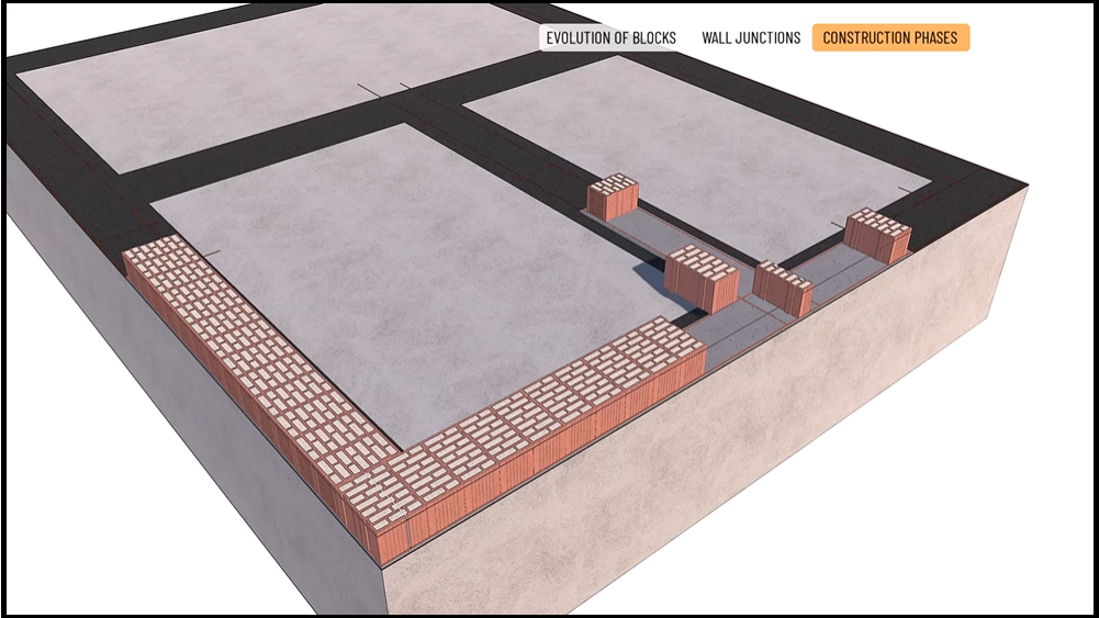
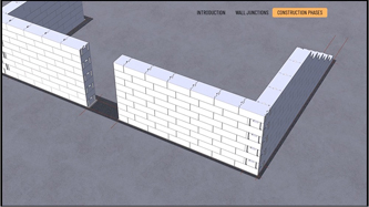
3. The phases of construction:
-
Above the foundation, on the surface of the reinforced concrete slab, we mark the external and internal contours of the walls, the wall corners, the wall connections, and the openings with a chalk line.
-
Horizontal damp proof course in 1 layer of modified bituminous membrane will be installed.
-
In the case of flat ground blocks, the perfect levelness of the first mortar layer is crucial because the minimum thickness of the joints in the subsequent courses will no longer allow for correction.
Adjustment is carried out using a mortar-levelling tool and a levelling bar.
The base layer of mortar is 2 to 3 centimetres thick, on which the setting points must be marked again. -
Next comes the positioning of the leads, which are adjusted with a rubber mallet and a level.
We start with whole blocks at the wall ends, a 19-centimetre closer at the wall corners, and a 12-centimetre closer at the Tee connection. -
Then comes the laying of the intermediate blocks for the first course of one of the 44-centimetre wall sections.
To do this, a line is stretched out between the set leads.
At the corner, we add a half bat to the three-quarter closer as planned and fill the space between the cut elements with adhesive.
The same is also done in all other cases where cut blocks meet other blocks.
The whole blocks are joined together by pushing the grooves and tongues into each other without using any adhesive. -
The intermediate blocks of the other wall section are laid similarly.
-
The first course of the 38-centimetre wall section is also built, and the joints are filled with adhesive.
-
The second course also starts with the laying of the leads.
We again start with a 19-centimetre closer in the wall-corners, but this time, the block faces the other way.
At the Tee connection, we place a 19-centimetre closer in the direction of the connecting 38-centimetre wall.
At each wall end, a half closer is now placed over the whole block. -
In all other respects, we will continue with the same masonry work as before.
The level and the plumb are checked regularly with a level.
-
-


-
-
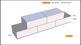
Introduction
Aerated concrete masonry block has excellent thermal insulation properties and low density, making it lightweight and fast construction possible.
Other advantages include good acoustic properties, plaster resistance, easy cutting and carving, and high dimensional accuracy.
Nowadays, blocks can be plain, hand-grip, or tongue-and-groove items. The blocks are laid in a stretcher course only, with typical lengths of 50 or 60 centimetres and widths of 30, 37.5 and 50 centimetres, which determine the wall thickness. The average height of the blocks is 20 centimetres.The typical joint size is 1 centimetre, which gives a course height of 21 centimetres. As it is shown, the plain blocks should be laid with a vertical mortar joint. In this case too, the blocks are laid according to the general rules for brick bonding, but the vertical joints do not have to be in the centre axis. However, the connection between the blocks must be at least 12.5 centimetres.
The preceding information also applies to hand-grip blocks, and mortar must be used for vertical gaps. However, the vertical joints of the tongue-and-groove blocks are already dry-built. Furthermore, in this case, only thin-bed masonry mortar can be used. This results in joints only two millimetres thick, which is both material-saving and significantly reduces the amount of thermal bridging. Particular attention must be paid to precisely adjusting the level of the first course, similar to thin mortar solutions for clay blocks.
Wall Junctions
Using a sample wall, we will investigate the wall connections of 37.5 centimetre-wide aerated concrete masonry block.
The type of blocks used is a tongue-and-groove one with handles, measures 37.5 x 60 x 20 centimetres.
The allocation of blocks is planned as follows:a) Wall corner - Start the course with a whole block from the corner in alternating courses, and the joints will be correct throughout the wall.
The wall thickness of 37.5 cm and an element length of 60 cm give an offset of 22.5 cm in both connecting walls, greater than the minimum requirement of 12.5 cm.b) Wall end - When forming the wall end, we also start with a whole block in the first course. In the next course, place a cut block on the wall end by the block bond plan. As previously planned, the cut blocks will be half, that is 30 cm.
c) Tee connection - In our example we assume that our main wall section already contains two wall corners, bonded as described earlier, with whole-element distances from the corners to the sides of the perpendicularly adjoining wall. Based on this the bonding overlaps are 22.5 centimetres in both directions, in a symmetrical setting.
We bond the adjoining wall to the main wall already in the first course, placing a whole block.
Because of the wall width of 37.5 centimetres, the piece of 60 centimetres length will overhang the main wall with 22.5 centimetres - this will be the overlap size in this wall section too.In our main wall two cut elements will be symmetrically placed upon the adjoining whole block, placing the joint on the center line of the joining wall.
The length of the cut elements is 56.5 centimetres, leaving a vertical joint of 1 centimetre that we fill with mortar.The construction phases are as follows:
-
We set the walls, connections, and openings on the reinforced concrete slab with a chalk line.
-
The damp proof course under the wall is fixed to the reinforced concrete slab, and the crucial points are marked again.
-
2-3 centimetres of mortar is applied for the first course using a trowel, a levelling tool and a levelling bar.
Place the whole blocks of the corner and the wall ends into the fresh mortar layer.
For the T-junction place two cut blocks symmetrically onto the central axis of the adjoining wall, and fill the vertical joint with mortar.
The size of the cut elements must be 48 cm so to maintain a half offset (30 cm) in this section of the wall, closed by the two wall ends.
The whole block of the adjoining wall butts into the main wall.
Use a levelling bar and a rubber mallet for horizontal and vertical adjustments. - A masonry cord is stretched out between the already placed blocks, and the filler (stretcher) masonry is done here.
The blocks will be laid along the original plan without any vertical mortar joints. - Check the levelness and sand the surface if there is more than one millimetre of unevenness.
- Starting from the next course, thin bed mortar is used, which is applied to the surface with a mortar roller.
- This time too, the key blocks are placed first: the whole block of the the T-junction and the half-bats of the wall ends.
- Again, we use masonry cords for laying the filler (stretcher) blocks.
- Using the levelling bar and rubber mallet, ensure the level and plumb as earlier, while alternating the two types of courses.
-
-

-
-
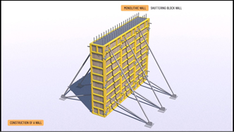
1. Monolithic Reinforced Concrete Wall
The cast-in-situ reinforced concrete wall has excellent load-bearing properties, but its thermal performance does not meet the requirements without additional external thermal insulation. Regardless, entire buildings can be constructed with reinforced concrete walls, and it is also very common to use them only in structurally-crucial locations. The latter is particularly true for the shear walls and shafts of reinforced concrete frame buildings. Unlike infill walls, they are structurally closely integrated with other reinforced concrete structures.
Casting requires formwork that can be removable or retained, that is remains in place. The former is often referred to as a single layer construction, while the latter is a sandwich structure.
The traditional solution for formwork is to assemble the mould from wooden planks. A modern version is the factory-assembled wall formwork reinforced with metal frames and stiffeners. There are also tunnel, climbing and slipform formwork technologies.The following is the technological sequence for the construction of a monolithic reinforced concrete wall with framed panels:
- Clean the formwork and apply the formwork release agent
- Assemble the front frame of the formwork on one side of the wall and support the structure with the push-pull props.
- Place the additional frames in a row, support them and connect the framed panels with clamps.
- Prepare, position and fix the reinforcement in the formwork.
- Assemble the opposite side of the formwork, install the form-ties while adjusting the wall thickness and propping the formwork.
- Carry out concreting as a single stage process, but in phases using concrete pumps and ready-mix concrete.
- Compact the concrete after this.
- Remove the formwork after two days of setting, but allow the wall 28 days to harden fully to the standard.
- After removing formwork in concrete structures, it is essential to cure it to avoid cracks and strength problems.
Therefore, the wall should be watered, damp, and protected from strong sunlight.
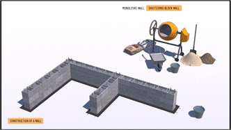
2. Shuttering Block Wall
Concrete is also used to make small-block masonry. Due to concrete’s good structural properties but poor thermal performance, it is mainly used for basement walls, fence foundations, terrace plinth walls, etc. A special form of these masonry blocks is the concrete shuttering block.
The shuttering block wall is a semi-monolithic structure, a multi-layer poured wall where hollow blocks with an outer shell and ribs of about 3 cm are stacked in a dry state without any bonding material and then poured with concrete using them as permanent formwork. The concrete core is typically strengthened with a structurally-sized reinforcement, significantly increasing the load-bearing capacity of the wall. Masonry and casting is done in stages, typically 2 to 3 courses at a time.
It is advisable to use a half offset over the entire masonry, as this guarantees that the cavities are properly aligned, helping to ensure that the vertical bars are properly and evenly spaced. Alternating between half and whole shuttering blocks can be used to build the wall corner, the Tee connection, and the wall end.
Construction of a shuttering block wall:
- Eliminate any unevenness during the preparation of the supporting structure.
- Mark the width of the masonry and the important nodes, and accurately set the height level with a tape measure.
- If necessary, provide a damp proof or waterproofing course under the walls so that it can be continued once the wall is finished.
The points of the setting are marked again on the waterproofing. - Place the starter course at the wall ends and wall corners, in 1-3 cm of perfectly levelled high-strength cement mortar.
- Carry out masonry according to the general rules of wall bonding, laying the blocks without any mortar.
The laying of the blocks should start at the wall-ends and wall corners.
The horizontal reinforcement is placed continuously in the prepared grooves and in the vertical direction, in lengths of 80 to 100 centimetres, so to overlap the subsequent courses. - Before pouring concrete, care must also be taken to ensure that the blocks are sufficiently wet.
Concreting, that is filling the cavities with concrete, is carried out every 2-3 courses.
Concrete can be either mixed in-situ or ready-mixed.
The former is typically cast with a shovel, and the in latter case the required quantity on concrete can be even pumped into its place.
The poured concrete should then be compacted by tamping.
To facilitate further construction, the top blocks should be filled only halfway with concrete.
-
-
-
In modern practice, pillars are most often made of reinforced concrete, less often of steel and even less often of wood or other materials.
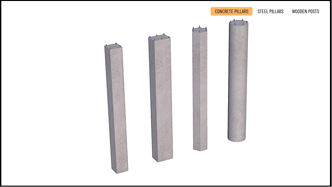
1. Reinforced Concrete Pillars
Monolithic reinforced concrete pillars can be formed with different cross-sections: square, rectangular, polygonal or circular. The reinforcement of the columns is composed of longitudinal rebars and stirrups of different density, corresponding to the static load. The mould can be traditional wooden shutter, or modern framed panel formwork.
A cast-in-situ reinforced concrete pillar can also be built with stay-in-place permanent formwork.
This permanent formwork can be a brick casing or built from concrete column shuttering blocks.In the case of the brick casing solution, the casing is built in stages, a reinforcement is placed and the cavity is filled with concrete in phases.
The desired height is reached in sections of 1.00 to 1.20 metres.In the case of concrete shuttering blocks, pour the concrete in one step after the full height has been reached and the reinforcement has been properly positioned.
The elements must also be wetted before concreting and during the finishing operations. The temporary bracings can be removed only after the concrete has fully hardened.
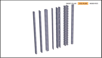
Finally, precast reinforced concrete pillars can be also placed. These are typically also placed in precast pocket foundation above the monolithic spread footing.2. Steel Pillars
Steel can be used to build lightweight, heavy-duty and small cross-section structures. They can be manufactured in cold bent or hot rolled sections.
Steel pillars can be made with different cross-sections:
- single columns can have I, H, C, Z or hollow profiles,
- columns can be formed by connecting several profiles by struts,
- truss structures can also be created from L profiles and horizontal or inclined struts,
- finally, we can also build columns of circular profiles.
A base and head plate are welded to the pillar to connect the steel stem to other elements. The connection can be reinforced with steel plates (stiffeners), which are also fixed by welding. The base and head plates can be used to bolt the column to the concrete base or to a steel beam.
Steel structures should be protected against rusting by galvanising or powder coating. In addition, fire safety considerations may require the application of various fire retardant coatings.
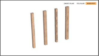
3. Wooden Posts
Modern wooden pillars can also be designed with a variety of cross-sections.As with steel piers, they can be made from a single piece of wood, factory-glued laminated beams, a combination of these, assembled from different beams with spacer blocks or tightly connected. In most modern practices, wooden columns do not meet the footing through a timber lower sill but are loaded directly onto a concrete spread footing or a reinforced concrete grade beam.
Direct contact between the two is dangerous for wood because prolonged contact with moisture can lead to wood decay. Therefore, the wooden posts always start above ground level, connected to the foundation slab or the spread footing through steel column shoes.
In addition, in modern practice, wooden columns must be made flame- and fungus-proof before they are installed. This process is called impregnation. A protective coating against the weather (sun, precipitation) can be applied by varnishing.
-